| Weight | 0.358 KG / psc. |
| Commodity number | 85364900 |
| Country of origin | CN |
| Dimensions (WxHxD) | 87x47x113 mm |
| EAN code | 3471523015357 |
| Product group | SB |
| eclass | V11.0 : 27371001 |
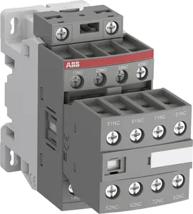
| etim 7 | EC000196 - Contactor relay |
| etim 8 | EC000196 - Contactor relay |
| unspsc | 39121500 |
| standards | IEC 60947-1 / 60947-4-1 and EN 60947-1 / 60947-4-1, UL 508, CSA C22.2 N°14 |
| operate time | Between Coil De-energization and NC Contact Closing 9 ... 20 msBetween Coil De-energization and NO Contact Opening 4 ... 18 msBetween Coil Energization and NC Contact Opening 7 ... 21 msBetween Coil Energization and NO Contact Closing 10 ... 26 ms |
| terminal type | Screw Terminals |
| cb certificate | https://library.abb.com/d/CB_SE-93051M2 |
| ul certificate | https://library.abb.com/d/UL_20191021-E312527_7_1 |
| cqc certificate | https://library.abb.com/d/CQC2019010303267993 |
| rohs information | https://library.abb.com/d/1SBD251089E1000 |
| climatic withstand | Category B according to IEC 60947-1 Annex Q |
| rated frequency (f) | Auxiliary Circuit 50 / 60 HzMain Circuit 50 / 60 Hz |
| degree of protection | acc. to IEC 60529, IEC 60947-1, EN 60529 Auxiliary Terminals IP20acc. to IEC 60529, IEC 60947-1, EN 60529 Coil Terminals IP20 |
| mounting on din rail | TH35-15 (35 x 15 mm Mounting Rail) acc. to IEC 60715TH35-7.5 (35 x 7.5 mm Mounting Rail) acc. to IEC 60715 |
| wire stripping length | Auxiliary Circuit 10 mmControl Circuit 10 mm |
| ambient air temperature | Close to Contactor for Storage -60 ... +80 °CNear Contactor for Operation in Free Air (0.85 ... 1.1 Uc) -40 ... 60 °CNear Contactor for Operation in Free Air (Uc) -40 ... 70 °C |
| tightening torque ul/csa | Auxiliary Circuit 11 in·lbControl Circuit 11 in·lb |
| rated operational voltage | Auxiliary Circuit 690 V |
| number of main contacts nc | 0 |
| number of main contacts no | 0 |
| object classification code | K |
| rated insulation voltage (ui) | acc. to IEC 60947-4-1 and VDE 0110 (Gr. C) 690 Vacc. to IEC 60947-5-1 and VDE 0110 (Gr. C) 690 Vacc. to UL/CSA 600 V |
| declaration of conformity - ce | https://library.abb.com/d/1SBD250026U1000 |
| declaration of conformity - ccc | https://library.abb.com/d/2020980303000175 |
| number of auxiliary contacts nc | 2 |
| number of auxiliary contacts no | 6 |
| declaration of conformity - ukca | https://library.abb.com/d/1SBD250047U1000 |
| data sheet, technical information | https://library.abb.com/d/1SBC100219C0201 |
| mounting by screws (not supplied) | 2 x M4 screws placed diagonally |
| rated control circuit voltage (uc) | 50 Hz 220 ... 230 V60 Hz 230 ... 240 V |
| connecting capacity control circuit | Flexible with Ferrule 1/2x 0.75 ... 2.5 mm2Flexible with Insulated Ferrule 1x 0.75 ... 2.5 mm2Flexible with Insulated Ferrule 2x 0.75 ... 1.5 mm2Rigid 1/2x 1 ... 2.5 mm2 |
| rated operational current ac-15 (ie) | (500 V) 2 A(690 V) 2 A(24 / 127 V) 6 A(220 / 240 V) 4 A(400 / 440 V) 3 A |
| rated operational current dc-13 (ie) | (24 V) 6 A / 144 W(48 V) 2.8 A / 134 W(72 V) 1 A / 72 W(110 V) 0.55 A / 60 W(125 V) 0.55 A / 69 W(220 V) 0.27 A / 60 W(250 V) 0.27 A / 68 W(400 V) 0.15 A / 60 W(500 V) 0.13 A / 65 W(600 V) 0.1 A / 60 W |
| connecting capacity auxiliary circuit | Flexible with Ferrule 1/2x 0.75 ... 2.5 mm2Flexible with Insulated Ferrule 2x 0.75 ... 1.5 mm2Flexible with Insulated Ferrule 1x 0.75 ... 2.5 mm2Rigid 1/2x 1 ... 2.5 mm2 |
| maximum electrical switching frequency | (AC-1) 0 cycles per hour(AC-15) 1200 cycles per hour(AC-2 / AC-4) 0 cycles per hour(AC-3) 0 cycles per hour(DC-13) 900 cycles per hour |
| maximum mechanical switching frequency | 6000 cycles per hour |
| maximum operating altitude permissible | Without Derating 3000 m |
| rated impulse withstand voltage (uimp) | 6 kV |
| resistance to shock acc. to iec 60068-2-27 | Closed, Shock Direction: B1 25 gOpen, Shock Direction: B1 5 gShock Direction: A 30 gShock Direction: B2 15 gShock Direction: C1 25 g |
| conventional free-air thermal current (ith) | acc. to IEC 60947-5-1, q = 40 °C 16 A |
| resistance to vibrations acc. to iec 60068-2-6 | 5 ... 300 Hz 4 g closed position / 2 g open position |
| rated short-time withstand current low voltage (icw) | for 0.1 s 140 Afor 1 s 100 A |